
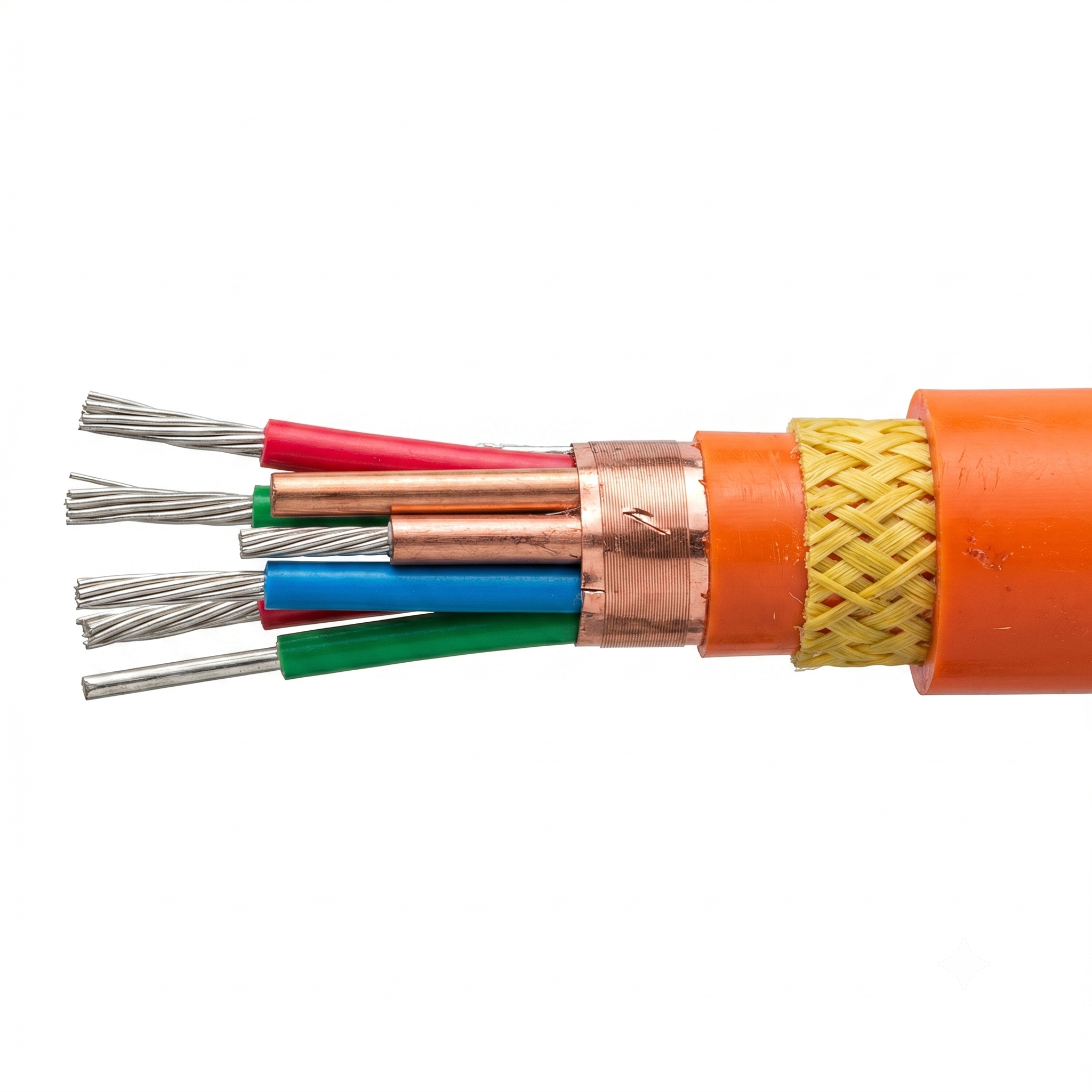
Photoelectric Composite Cable for Marine and Underwater Systems
Photoelectric composite cable is designed for marine, underwater, offshore, and tethered systems that need fiber optic, power, and signal transmission in one cable. With high-watertight construction, single-mode or multimode fiber options, power conductors, shielded signal wires, twisted shielded pairs, and high-tensile reinforcement options, it supports demanding underwater communication, power supply, and control applications.
Fiber + Power + Signal
High-Watertight Design
Marine & Underwater Use
Overview
Photoelectric Composite Cable is designed for marine, underwater, offshore, and tethered systems that require optical fiber transmission, electrical power, signal wiring, and mechanical reliability in one integrated cable construction.
This product family uses a hybrid optical and electrical structure to transmit multiple optical signals, electrical signals, and power at the same time. Depending on the selected model, the cable can support single-mode fiber, multimode fiber, power conductors, shielded wires, shielded twisted pairs, high-tensile reinforcement, high-watertight construction, and repeated deployment requirements.
This page is intended for product selection. Exact specifications should be confirmed by fiber type, fiber count, power conductor layout, shielded wire count, shielded twisted pair count, tensile strength, sheath material, reinforcement structure, water-tightness requirement, outside diameter, and project drawing before ordering.
Series Options
The table below helps buyers understand the main photoelectric composite cable options before reviewing drawings, technical specifications, or test requirements.
| Series Option | Product Positioning | Typical Selection Scenario |
|---|---|---|
| Fiber + Power Composite Cable | Hybrid cable with optical fibers and power conductors | For underwater or marine systems requiring optical communication and power transmission in one cable. |
| Fiber + Signal Composite Cable | Hybrid cable with optical fibers, shielded signal wires, or shielded twisted pairs | For systems requiring optical communication together with electrical signal transmission and interference protection. |
| High-Tensile Composite Cable | Photoelectric composite cable with high tensile strength | For tethered, deployed, or underwater equipment where the cable must support mechanical load while transmitting fiber optic, power, or signal functions. |
| High-Watertight Composite Cable | Photoelectric composite cable for underwater and marine applications | For underwater systems requiring reliable sealing, high water resistance, and stable optical-electrical transmission. |
| Neutral Buoyancy Option | Special photoelectric composite cable option with neutral buoyancy design | For selected underwater applications where buoyancy control is required. This is model-specific and should be confirmed by project requirement. |
| BYC Custom | Custom photoelectric composite cable construction | For projects requiring custom fiber count, fiber type, power conductors, shielded wires, shielded twisted pairs, tensile strength, sheath, water-tightness, diameter, weight, or documentation support. |
Features
Optical and Electrical Composite Design
Combines optical fibers, power conductors, shielded wires, and shielded twisted pairs in one integrated cable construction.
Single-Mode and Multimode Fiber Options
Supports single-mode and multimode fiber options depending on communication distance, bandwidth, and system design.
High-Watertight Construction
All listed product types are designed to support high-watertight requirements for marine and underwater applications.
High-Tensile Options
Representative constructions support tensile strength from low-load designs to high-strength options up to 250kN.
Repeated Deployment Support
Designed for marine systems that may require repeated deployment, recovery, bending, and underwater operation.
Custom Composite Layout
BYC Cables can review custom layouts for fiber count, power wires, shielded signal wires, shielded twisted pairs, sheath, reinforcement, and testing.
Construction & Materials
Photoelectric composite cables are project-specific hybrid cables. Final construction should be selected according to optical transmission, power load, signal transmission, tensile strength, watertight performance, sheath material, reinforcement method, cable outside diameter, and deployment environment.
Construction Options
| Component | Available Options | Selection Notes |
|---|---|---|
| Optical Fiber | Single-mode fiber or multimode fiber options | Fiber type should be selected according to communication distance, bandwidth, optical attenuation, and system design. |
| Fiber Structure | Loose-tube fiber or tight-buffered fiber options | Loose-tube and tight-buffered structures should be selected according to bending, protection, installation, and deployment requirements. |
| Power Conductors | Custom power conductor count and cross-section based on load requirement | Power conductor selection should be confirmed by voltage withstand, current load, cable length, and voltage drop requirement. |
| Shielded Wires | Shielded wire quantity varies by selected model | Shielded wires can support electrical signal transmission and reduce interference in marine and underwater systems. |
| Shielded Twisted Pairs | Shielded twisted pair quantity varies by selected model | Twisted shielded pairs are suitable for differential signal, data, or communication circuits requiring better signal integrity. |
| Reinforcement | Aramid reinforcement or metal reinforcement depending on construction | Reinforcement should be selected according to tensile strength, cable weight, flexibility, and deployment method. |
| Sheath Material | Polyethylene or polyurethane sheath options | Sheath selection should consider abrasion resistance, water exposure, flexibility, and marine environment. |
| Insulation Material | Fluoroplastic insulation or project-specified insulation options | Insulation should be selected according to voltage withstand, signal performance, and environmental requirements. |
| Buoyancy | Neutral buoyancy option is available for selected model only | Neutral buoyancy should be treated as a project-specific option, not a standard feature for all models. |
Construction Differences
| Cable Type | Construction Focus | Confirmed Information | When to Choose |
|---|---|---|---|
| Hybrid Fiber + Power Cable | Optical fiber and power conductor integration | Selected models combine single-mode or multimode optical fibers with power conductors in one high-watertight cable. | Choose when underwater equipment needs both optical communication and electrical power supply. |
| Hybrid Fiber + Signal Cable | Optical fiber with shielded signal wires or shielded twisted pairs | Selected models include shielded wires, shielded twisted pairs, or both, with quantities depending on the model. | Choose when the system needs optical communication together with electrical signal or data transmission. |
| High-Tensile Composite Cable | Composite cable with tensile reinforcement | Representative tensile strength values include 1kN, 6kN, 8kN, 10kN, 60kN, 100kN, 200kN, and 250kN depending on selected model. | Choose when the cable must support mechanical load during deployment, recovery, or underwater operation. |
| Neutral Buoyancy Composite Cable | Special buoyancy-controlled photoelectric composite cable | Neutral buoyancy is available for one representative model and should be confirmed by project requirement. | Choose when underwater cable buoyancy control is required for system deployment or operation. |
| BYC Custom | Custom optical-electrical composite cable construction | Fiber count, fiber type, conductor layout, shielded wires, shielded twisted pairs, sheath, reinforcement, water-tightness, and test requirements can be reviewed. | Choose when representative models do not fully match the system interface, mechanical load, transmission function, or underwater environment. |
Specifications
The specifications below are intended for preliminary product selection. Final values should be confirmed according to optical fiber type, conductor layout, shielded wire count, shielded twisted pair count, tensile strength, sheath material, water-tightness requirement, and project drawing.
| Product Family | Photoelectric Composite Cable for Marine and Underwater Systems |
|---|---|
| Main Function | Integrated fiber optic, power, and electrical signal transmission |
| Main Applications | Marine systems, underwater equipment, offshore devices, tethered systems, optical-electrical transmission, power supply, signal transmission, and communication systems |
| Optical Fiber Options | Single-mode fiber and multimode fiber options are available depending on selected construction. |
| Electrical Transmission | Power conductors, shielded wires, and shielded twisted pairs can be integrated depending on selected model and project requirement. |
| Water-Tightness | All listed product types are designed to support high-watertight marine and underwater requirements. |
| Tensile Strength | Representative tensile strength values range from 1kN to 250kN depending on selected model. |
| Voltage Withstand | Representative values include 1.0kV, 1.5kV, 2.0kV, 2.5kV, and 4.0kV AC depending on selected model. |
| Optical Attenuation | Representative values include ≤0.4dB/km at 1310nm, ≤0.3dB/km at 1550nm, ≤3.0dB/km at 850nm, and ≤1.0dB/km at 1300nm depending on fiber type and model. |
| Sheath Material | Polyethylene or polyurethane sheath options |
| Insulation Material | Fluoroplastic insulation or project-specified insulation options |
| Reinforcement | Aramid reinforcement or metal reinforcement depending on selected construction |
| Neutral Buoyancy | Available for selected model only and should be confirmed by project requirement. |
| Operating Temperature | Operating temperature should be confirmed by selected sheath material, insulation system, reinforcement structure, and project requirements. |
| Reference Standards | Reference standards may include GJB1428B-2009, GJB1916-1994, and MIL-DTL-24643C:2009 depending on selected cable type. These should be treated as reference standards, not third-party certifications. |
| Customization | Available based on drawings, samples, optical fiber requirements, power and signal layout, tensile strength, water-tightness requirements, and documentation needs. |
For accurate quotation, please provide the required fiber type, fiber count, power conductor count, shielded wire count, shielded twisted pair count, tensile strength, sheath material, water-tightness requirement, outside diameter target, and applicable drawings or specifications.
Representative Technical Specifications
| Model | Cable OD | Voltage Withstand | Optical / Electrical Structure | Tensile Strength | Optical Attenuation |
|---|---|---|---|---|---|
| GTFSU-4B1-10×37×0.31 / 4×2×0.5 | 32.5±0.3mm | 2.5kV AC | 4 single-mode fibers, 10 power wires, 3 shielded wires, 4 shielded twisted pairs | 250kN | ≤0.4dB/km @1310nm; ≤0.3dB/km @1550nm |
| GTFJYH-4B1-4×19×0.31 | 13.5±0.3mm | 1.0kV AC | 4 single-mode fibers, 4 power wires | 6kN | ≤0.4dB/km @1310nm; ≤0.3dB/km @1550nm |
| GTFSYU-4A1-4×19×0.29 | 23.0±0.5mm | 2.0kV AC | 4 multimode fibers, 4 power wires | 200kN | ≤3.0dB/km @850nm; ≤1.0dB/km @1300nm |
| GTFYU-4A1-4×19×0.26 / 6×2×7×0.2 | 18.0±0.3mm | 1.0kV AC | 4 multimode fibers, 6 shielded twisted pairs | 60kN | ≤3.0dB/km @850nm; ≤1.0dB/km @1300nm |
| GTFSU-4A1-4×37×0.37 | 16.7±0.3mm | 1.0kV AC | 4 multimode fibers, 4 power wires, steel wire armored, polyurethane sheath | 60kN | ≤0.4dB/km @1310nm; ≤0.3dB/km @1550nm |
| GTFYU-3A1-2×19×0.51 / (4P+4)×2×7×0.2 | 23.0±0.3mm | 1.0kV AC | 3 multimode fibers, 4 unshielded twisted pairs, 4 shielded twisted pairs | 1kN | ≤3.0dB/km @850nm; ≤1.0dB/km @1300nm |
| GTFSYU-4B1-2×37×0.37 | 18.7±0.3mm | 4.0kV AC | 4 single-mode fibers, 2 power wires, tin-phosphor copper braided sheath | 100kN | ≤0.4dB/km @1310nm; ≤0.3dB/km @1550nm |
| GTFJYFU-2A1-11×19×0.26 / 14×19×0.15 / 7×2×7×0.2 | 23.5±0.3mm | 1.5kV AC | 2 multimode fibers, 11 × 1mm² wires, 14 × 0.35mm² wires, 7 shielded twisted pairs | 10kN | ≤3.0dB/km @850nm; ≤1.0dB/km @1300nm |
Applications
Photoelectric composite cables are suitable for marine and underwater systems that require optical communication, power supply, signal transmission, water-tightness, tensile strength, and long-term deployment reliability.
Underwater Communication Systems
For underwater equipment requiring optical fiber communication together with power or electrical signal transmission.
Marine Tethered Equipment
For tethered marine systems that need high-watertight construction and integrated optical-electrical transmission.
Offshore and Subsea Devices
For offshore platforms, subsea devices, and underwater monitoring systems requiring durable hybrid cable performance.
Power and Fiber Integration
For systems requiring both electrical power supply and fiber optic data transmission in one compact cable assembly.
Signal and Data Transmission
For underwater systems requiring shielded wires, shielded twisted pairs, or differential signal transmission together with optical fibers.
High-Tensile Deployment Systems
For applications requiring high tensile strength, repeated deployment, recovery, and mechanical reliability.
Selection Guide
Use this guide as a starting point. Final selection should be confirmed by fiber type, electrical layout, tensile strength, water-tightness, sheath material, optical attenuation, outside diameter, and deployment environment.
| Requirement | Recommended Option | Selection Reason |
|---|---|---|
| Long-distance optical communication | Single-Mode Fiber | Single-mode fiber options are suitable for longer-distance optical transmission and lower attenuation at 1310nm / 1550nm. |
| Shorter-distance multimode transmission | Multimode Fiber | Multimode fiber options are available for systems using 850nm / 1300nm transmission windows. |
| Power + fiber integration | Fiber + Power | Choose composite constructions that integrate optical fibers and power conductors in one cable. |
| Fiber + signal integration | Shielded Signal | Choose models with shielded wires or shielded twisted pairs when electrical signal transmission is also required. |
| High tensile strength | High-Tensile | Representative models support tensile strength up to 250kN depending on selected construction. |
| Buoyancy control | Neutral Buoyancy | Neutral buoyancy is available for selected model only and should be confirmed during project review. |
| Project-specific cable layout | BYC Custom | BYC Cables can review fiber count, power wires, signal wires, shielding, sheath, tensile strength, diameter, and testing requirements. |
Customization Options
BYC Cables can support custom photoelectric composite cable requirements based on drawings, samples, system interfaces, underwater conditions, and project documentation needs.
Fiber Type and Count
Single-mode or multimode fiber and custom fiber count can be reviewed according to optical communication requirements.
Power Conductors
Power conductor count and conductor size can be selected according to voltage, current, cable length, and voltage drop requirements.
Shielded Signal Wires
Shielded wire quantity can be customized according to signal transmission and interference protection requirements.
Shielded Twisted Pairs
Shielded twisted pair quantity can be reviewed for differential signal, data, or communication circuits.
Tensile and Reinforcement Design
Tensile strength, aramid reinforcement, metal reinforcement, and mechanical structure can be designed according to deployment conditions.
Sheath, Buoyancy and Testing
Polyethylene or polyurethane sheath, buoyancy requirements, water-tightness, optical attenuation, voltage withstand, and inspection documentation can be reviewed.
Request a Quote
Please provide the required fiber type, fiber count, power conductor count, shielded wire count, shielded twisted pair count, tensile strength, water-tightness requirement, sheath material, outside diameter target, buoyancy requirement if any, and applicable drawings or specifications.
FAQ
What is a photoelectric composite cable used for?
It is used for marine and underwater systems that require optical fiber communication, electrical power, and signal transmission in one integrated cable.
Can this cable include both power conductors and optical fibers?
Yes. Selected constructions can integrate optical fibers, power conductors, shielded wires, and shielded twisted pairs depending on project requirements.
Are single-mode and multimode fiber options available?
Yes. Single-mode and multimode fiber options are available. The final fiber type should be selected according to communication distance, bandwidth, and system design.
Do all models support high-watertight requirements?
Yes. The listed product types are designed to support high-watertight requirements for marine and underwater applications. Final test requirements should be confirmed by project specification.
Is neutral buoyancy available?
Neutral buoyancy is available for selected model only. It should be confirmed during project review instead of being treated as a standard feature for every construction.
What information should I provide for quotation?
Please provide fiber type, fiber count, power conductor count, shielded wire count, shielded twisted pair count, tensile strength, sheath material, water-tightness requirement, outside diameter target, and any drawings or technical standards.
contact us
STEP 1
Inquiry Received
-
Instant acknowledgment and
dedicated specialist assignment.
STEP 2
Technical Review
-
Expert evaluation of specifications
for optimal reliability.
STEP 3
24H Response
-
Comprehensive proposal and
competitive pricing within 24 hours.